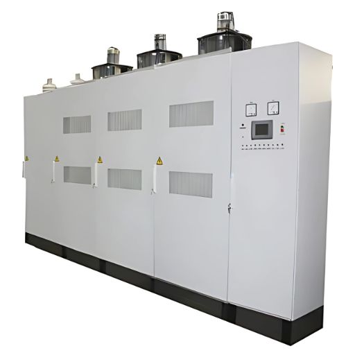
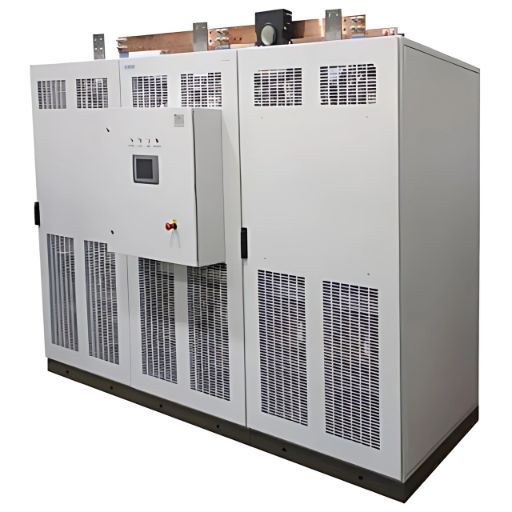
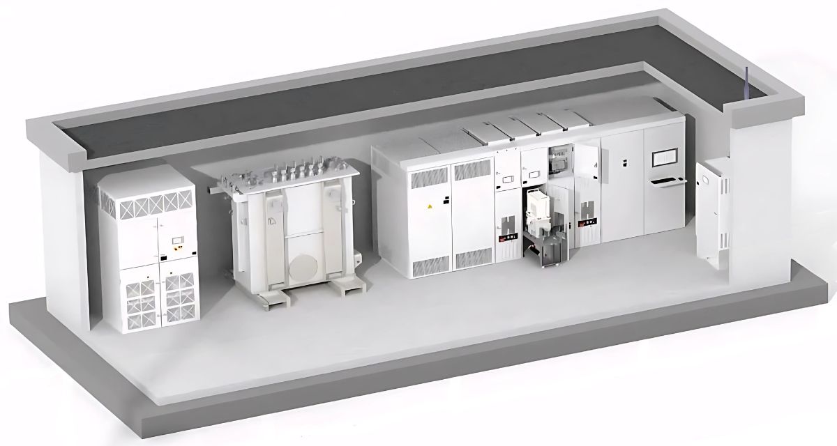
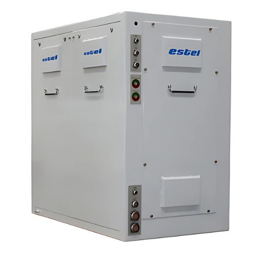
TPRS Series
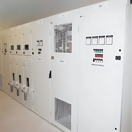
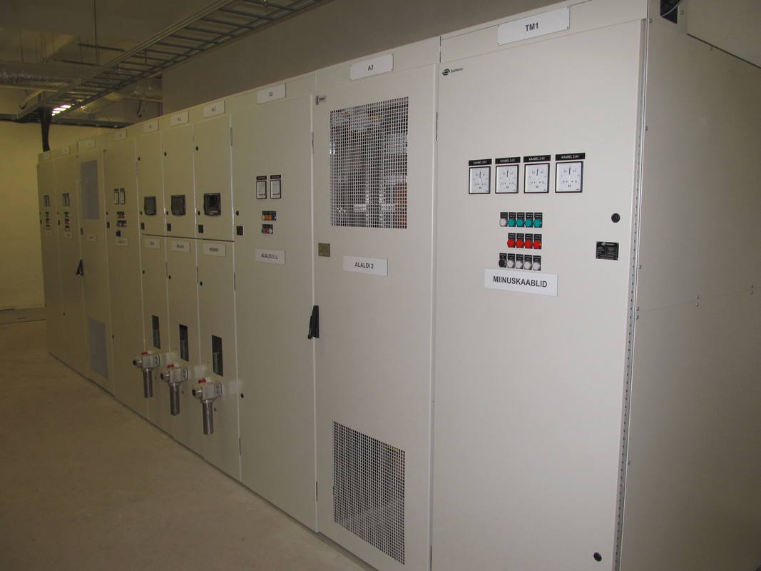


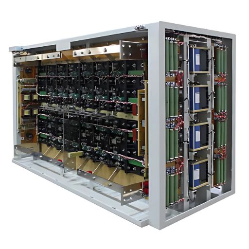
In the standard design the rectifier is assembled according to 12-pulse current rectification circuit formed by subsequent connection of two bridges. However, 6-pulse rectifier circuit is also possible. Natural cooling ensures high reliability and overload capacity, maintenance is not required in the course of operation. Use of a common heatsink on two parallel diodes is a block minimizes quantity of buses and transitional contacts leads to reduced losses. Assembly includes a custom-made clamping mechanism allowing quick replacement of diodes without the need of neither removing the power equipment nor using special tools.
Rectifier can be executed in two options:
- single or double bridge topology,
- two reverse stars with current-balancing reactor.
Quantity of the diodes in a branch may be increased to n+1 to increase unit’s operational reliability. Each diode is provided with the conductivity diagnostic circuit.
Control system is based on TET ESTEL manufactured controller. Operator’s control panel is equipped with an LCD display.
Protection and diagnostic system:
- The rectifier is equipped with overheat protection system, door safety locks, button of high voltage emergency stop switch.
- The rectifier is fitted with microprocessor protection and diagnostic system based on the TET ESTEL designed and manufactured controller and is equipped with operator’s control panel with a large LCD display.
- The microprocessor control system equipped with an oscilloscope allows to perform continuous monitoring of the unit parameters, e.g. current, voltage, diode conductivity, temperature, waveform etc. Parameter values are saved in the unit’s internal memory and can be retrieved later for analysis. Control system generates alarm signals in case of faults, if they occur, and forwards them according to the process protocol.
- Connection of rectifier controller with upper level system (central control station) is possible via various connection options: analogue signals or RS232 / RS485 interface with the use of MODBUS data communications protocol.
- Designed to comply with RoHS and REACH requirements.
| Rated output power range, kW | 720 - 2600 |
| Rated output voltage, VDC | 600 - 850 |
| Rated output current range, А | 1200 - 3150 |
| Allowed over-current time: *RMS value for every 24 hours should not exceed rated current value ** RMS value for every 8 hours should not exceed rated current value | @125 % – 2 hours, 2 times per 24 hours* |
| @150 %– 300 s, 1 time per 30 min** | |
| @200 % – 60 s, 1 time per 30 min** | |
| Rated input voltage range, V | 475 - 650 |
| Input voltage frequency, Hz | 50 ; 60 |
| Input voltage phases | 3 |
| Rated input current range, А | 1000 - 2570 |
| Cooling | natural air |
| Power factor (calculated), minimum | 0,94 |
| Efficiency (calculated), minimum | 0,98 |
Protection class: | |
| — power circuit | IP21 |
| — control system | IP54 |
| Ambient temperature range, °С | from minus 25 to +45 |
| Max. relative air humidity at +25°С, % | 98 |
| Max. altitude above sea level, m | 1400 |
